This post concludes my quatrology of essays touching on peculiarities of the reactor accident at the Fukushima I (Daiichi) Nuclear Power Station on the northeastern coast of Japan as a result of the Tohoku-Oki Earthquake and Tsunami on Mar. 11, 2011. I will continue to update the content of the series as new information crucial to the discussed issues becomes available.
This essay once more is of technical nature, seeking to examine potential system failures that led to the fuel core melt-downs and melt-throughs at the three reactor units that were producing power at the Fukushima Daiichi Nuclear Power Station on the day of the earthquake and tsunami. The fourth unit with extensive damage was shutdown at the time and the fuel was stored in its spent fuel pool. Forceful explosions resulted from excessive accumulation of hydrogen in the buildings of the four units. The hydrogen was produced by radiolysis and oxidation of the cladding of superheated fuel rods. Radioactive material in amounts only superseded by the Chernobyl reactor accident, 1986, was released into the atmosphere and into the ocean with yet unfathomable consequences for public health. The lives of hundreds of thousands of residents around the plant will be profoundly affected. Fukushima Prefecture alone is home to roughly 3 million people.
The calamity has been unfolding on the heel of the utter destruction of coastal villages and towns owing to the earthquake and tsunami. According to the Report of the Japanese Government to the IAEA Ministerial Conference on Nuclear Safety, page III-10, released last month, 24,769 persons were reported dead or still missing on May 30, 2011. The examination of technicalities of the reactor disaster must pale compared with the human toll exacted. However, this essay may help shine a light on shortcomings in design that may pertain as well to other nuclear power reactors around the world and help prevent yet another disaster that added in unprecedented ways to this human tragedy of mind-shattering proportion.
 |
| Schema of a boiling water reactor (BWR) with a Mark I primary containment system consisting of the pear-shaped drywell and the ring-shaped suppression chamber which contains a pool of water used to depressurize the containment when needed. The drywell houses the reactor pressure vessel (maroon) with the fuel core in which steam is produced for power generation (courtesy NRC). |
The video below provides an overview on BWR-3 reactors and Mark I containment systems in the US and a good impression of the structures' dimensions:
Though Units 1, 2 and 3 incurred loss of coolant accidents with fuel core melt-downs and, very possibly, melt-throughs penetrating their primary containments, differences in design, particularly of systems that cool reactor cores and vent gas and steam, may help explain the observed differences in event sequence and thrust.
The reactor turbine feed loop represents the main circulation loop for steam and water during normal reactor operations, transferring the heat generated by nuclear fission to the turbine that drives the electric power generator. Water condensed in the turbine condensers continuously replenishes coolant in the 500-m3 reactor pressure vessel (RPV), preventing the fuel core from overheating. In addition to serving as coolant, water is used to moderate neutron fluxes between the fuel rods, enabling a controlled, sustained nuclear chain reaction.
After a seismic SCRAM like at Fukushima, main steam isolation valves shut the turbine loop off. Though the safety rods are inserted to stop nuclear fission, decay of neutron-activated radioactive isotopes continues to produce heat which keeps the reactor water temperature above boiling. Steam and pressure build in the RPV. Once a setpoint is reached, the safety/relief valves of the automatic depressurization system (ADS) succinctly depressurize the RPV to prevent damage to the vessel, venting steam into the suppression pool. As a consequence of the depressurization, the water level in the RPV falls rapidly unless water is injected. The emergency core cooling system, or ECCS for short, consists of several interrelated standby systems that can be used to achieve replenishment with auxiliary feedwater.
 |
| Schema showing IC (BWR-3) and RCIC (BWR-4) standby cooling systems (Stoll U, 2011). |
In BWR-4s, by contrast, the IC is replaced with the reactor core isolation cooling (RCIC) system [USNRC Technical Training Center, Boiling Water Reactor GE BWRA4 Technology Technology Manual (Rev 0197), Chapter 2.7: Reactor Core Isolation System]. At Fukushima Daiichi, the RCIC and the HPCI are housed in rooms on the northern and southern corner, respectively, on the first basement level outside the western wall of the reactor buildings. The main component of the RCIC system is a turbine-driven pump which can discharge water through the uppermost feedwater line into the RPV at 400 gallons, or roughly 1.5 m3, per minute. Compared to the HPCI at 19 m3 per minute and the LPCI at 150 m3 per minute, the RCIC's capacity seems small. Its pump would need five hours and a half to fill the entire RPV. However, the rate suffices to replace the boil-off anticipated 15 minutes after shutdown.
 |
|
Control room whiteboard with operator notes on Unit 2 through the first hour after the seismic SCRAM. The entry at 15:01 mentions the RCIC system the first time (courtesy TEPCO).
|
The Terry Corporation, now part of Dresser-Rand, manufactured most turbines of the kind used to drive RCIC pumps in US BWRs. Reaching full capacity within two minutes from start-up, the pumps are aligned by default to remove water from the condensate storage tank, also known as the contaminated condensate storage tank, and inject it into the RPV. If tank water is unavailable or if the suppression chamber pool reaches a preset level, valves automatically direct the suction path via a 16-inch pipe to the torus.
 |
| Example of a Terry RCIC turbine. |
Outboard piping downstream from the pump is commonly not as seismically resistant as the inboard piping from the suppression chamber which is considered existential to reactor safety. If the RCIC design at the Fukushima Daiichi reactors had been the same as that mandated in the US, the inferior seismic rating of the parts of the RCIC loop downstream of the pump could have contributed significantly to the inability of delivering adequate coolant to Units 2 and 3 after the earthquake.
According to Jake Adelstein and David McNeill's post with the title "Meltdown: What Really Happened at Fukushima?" published online in the Atlantic Wire on Jul. 2, 2011, eyewitnesses report that the earthquake immediately inflicted widespread, substantial damage to piping at the station. The quake may have ruptured less seismically-hardened RCIC piping, providing a continuous escape route for coolant, steam, and non-condensible gases, e.g. hydrogen and radioactive noble gases, from the suppression chamber. The suppression chamber pool, however, supplies the coolant for the emergency core cooling system.
According to Jake Adelstein and David McNeill's post with the title "Meltdown: What Really Happened at Fukushima?" published online in the Atlantic Wire on Jul. 2, 2011, eyewitnesses report that the earthquake immediately inflicted widespread, substantial damage to piping at the station. The quake may have ruptured less seismically-hardened RCIC piping, providing a continuous escape route for coolant, steam, and non-condensible gases, e.g. hydrogen and radioactive noble gases, from the suppression chamber. The suppression chamber pool, however, supplies the coolant for the emergency core cooling system.
 |
| This photograph taken May 10, 2011, added Feb. 27, 2012, shows the pair of steam vent pipes for isolation condenser subsystem A and B, exiting the reactor building of Unit 1 in the middle of the wall immediately under the refueling floor. Note the vent pipe surrounded by debris is uncapped. This must be the vent from which steam was observed emanating in the hours after the quake (courtesy Daisuke Tsuda). |
 |
| Vent stack on northwest corner of the reactor building of Unit 2. |
Roughly 29 seconds into the report below, the footage suggests that steam was already emanating from the reactor building rooflines when the first tsunami waves arrived, probably through these short stacks.
At 15:29, that is approximately the same time the footage above was recorded, a monitor about a mile from the reactor buildings sounded radiation alert according to Yuji Okada, Tsuyoshi Inajima and Shunichi Ozasa's post with the title "Fukushima May Have Leaked Radiation Before Tsunami" published online on Bloomberg News May 19, 2011. The source of the radioactivity may have been contaminated steam from the suppression chamber, escaping through the short stacks via damaged valves and broken piping of standby cooling systems like the RCIC. Once the fuel rods in the reactor core super-heated because of the persistent loss of coolant, their zircalloy cladding reacted with water to produce large amounts of hydrogen that accumulated in the reactor buildings, until the gas detonated in violent explosions.
It is important to note that neither the widely-acknowledged extended offsite power outage nor the failure of onsite emergency diesel generators may have caused the standby coolant systems to malfunction. Rather, the constant leakage of coolant through shattered loops in these systems may have prevented effective reactor core cooling and may have been detrimental to further attempts of cooling with the addition of seawater during the days after the earthquake and tsunami. The loss of coolant eventually would lead to extensive uncovering of reactor fuel cores, core melt-downs and the eventual melt-throughs of highly radioactive material.
The operator of the Fukushima Daiichi Nuclear Power Station known as Tokyo Electric Power Company, or TEPCO for short, apparently paid little heed to maintenance and improvements of emergency equipment instrumental for a successful cold shutdown after a loss of coolant accident. TEPCO's probabilistic risk assessment predicted a temblor of the strength of the Tohoku-oki Earthquake to happen only once in ten-thousand years or less (Report of the Japanese Government to the IAEA Ministerial Conference on Nuclear Safety, figure III-2-3, page III-39). Loss of coolant accidents may be met by similarly anemic standby cooling systems at any nuclear power station with such reactors in an earthquake zone.
Acknowledgement
This post would have been impossible without the contributors to Japan Earthquake Live and the invaluable information on SimplyInfo.org.
Related Posts
- Seismic Activity & Reactor Safety: Lessons from Japan
- The Enigma of 1 Fukushima 4 号機
- Fukushima: Failure of the Mind
- Ionizing Radiation & The Mind
- According to the report of Japan's Nuclear and Industrial Safety Agency (NISA) to the International Atomic Energy Agency with the title "Report of Japanese Government to the IAEA Ministerial Conference on Nuclear Safety - The Accident at TEPCO’s Fukushima Nuclear Power Stations -", June 2011, Unit 1 possessed two redundant isolation condensers and a high pressure coolant injection (HPCI) system, whereas the other units were equipped with one RCIC system and one HPCI system. The HPCI system consists of a turbine-driven pump and a turbine-driven booster pump which can be used when the RPV pressure approaches design basis. The suction paths are the same as for the RCIC (07/6/11):

NISA system diagram of Unit 1 (Fig. IV-2-1), showing two isolation condensers on the left of the reactor.

Flow Rates for Standby Cooling Systems at Fukushima Daiichi Nuclear Power Station according to the NISA report to the IAEA in June, 2011, Tab IV-2-1 (07/06/11).
| Unit | 1 | 2 | 3 |
| HPCI | 14.7 | 16.0 | 16.0 |
| LPCI | N/A | 116 | 128 |
| RCIC | N/A | 1.6 | 1.6 |
- NISA's report confirms the above cited claim by Bloomberg News that elevated levels of radioactivity were detected on the station premises after the quake and before the tsunami. I quote from the report's page V-18:
“After the earthquake, measured values of GM measuring tubes were higher than usual in reactor facilities, while values measured at monitoring posts installed in the surrounding monitoring areas of Fukushima Dai-ichi NPS showed no anomaly. (Attachment V-9 Measured results of monitoring posts)” (07/18/2011).
- In addition, on page 12 of NISA's report, we find the following description of the attempts of cooling the core of Fukushima Daiichi Nuclear Power Station's Reactor 3 after the earthquake and tsunami:
“The Reactor Core Isolation Cooling System (RCIC) was manually started at 15:05 on March 11. It stopped automatically at 15:25 on the same day due to the rise of the reactor water level. It was started manually at 16:03 on the same day, and the RCIC stopped at 11:36 on March 12. The High Pressure Core Injection System (HPCI) automatically started due to the reactor low water level (L-2) at 12:35 on the same day, and the HPCI stopped at 2:42 on March 13. The reason for that appears to be a drop of pressure in the reactor. The other probable cause could be water-vapor outflow from the HPCI system.”
NISA hypothesizes further:
“..., the fuel appears to have been exposed due to a drop of the reactor water-level at around 08:00 on March 13, and the core started melting afterwards.”
On Jul. 28, 2011, TEPCO released a handout with the title "Factors of fluctuation in plant parameters such as reduction of the pressure in Reactor during operation of High Pressure Coolant Injection System" with which the company hopes to clarify that the HPCI coolant loop remained intact, contrary to speculations proffered earlier in the NISA report. Inspection of the graphs provided in this document shows that the RCIC system resumed function one more time shortly after noon on Mar. 12 and stopped again in the early morning hours of Mar. 13.
 |
|
RPV water level time courses for Unit 3, based on trial analysis with a Modular Accident Analysis Program (MAAP) and measurements. Matching up time lines, RICI is synonymous with RCIC system.
|
In accord with the hypothesis entertained in my post, RCIC failure remains the most likely cause that precipitated the reactor's demise. During the morning hours of Mar. 13 after the RCIC had come to its final halt, RPV pressure rose rapidly and its water level dropped decisively, uncovering the core.
 |
|
RPV pressure level time courses for Unit 3, based on trial analysis with a Modular Accident Analysis Program (MAAP) and measurements. RICI is synonymous with the RCIC system.
|
A safety/relief valve was opened, relieving the pressure into the primary containment at around 9:00 on Mar. 13. At 5:20 on the following day, the operators vented the suppression chamber with hardened venting. At 11:01, a massive hydrogen explosion severely damaged Unit 3 (07/29/11).
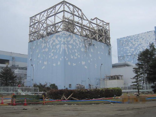
According to the Shift Supervisor Task Handover Journals for Units 1,2 and Units 3,4 released by TEPCO, the condensate storage tanks were about two-thirds filled on March 11. The volume could have fed the RCIC pumps for roughly 19 hours. Once the water in the tanks was running low, the operators had to switch the suction isolation valves, setting the suction path to the suppression chamber of the primary containment as alternate source for the RCIC and HPCI systems. At Unit 2, the tank was two-thirds full. The supply should have lasted for 16 hours, if it had been used for the RCIC system alone. In actuality, it lasted only 12 to 13 hours. According to the update of the Government of Japan to the International Atomic Energy Agency with the title "Additional Report of Japanese Government to IAEA - Accident at TEPCO's Fukushima Nuclear Power Stations Transmitted by Nuclear Emergency Response Headquarters, Government of Japan, 15 Sep 2011", page II-93, “from 04:20 to 05:00, March 12, as water level of the Condensate Storage Tank (CST) decreased and also in order to control rising of the S/C (suppression chamber) water level, the water source for the RCIC was switched from the CST to the S/C for the RCIC to continue injecting water.” The change of source appears to have accelerated the reactor's demise. The suction isolation valves may have failed (10/30/2011). Photograph taken Oct. 3, 2008. The reactor buildings of Unit 1 (top, slightly offset toward the right) to 4 (bottom) are situated on the the left, the turbine buildings on the right (cryptome.org). The condensate storage tanks consist of the four large white tanks in front of the turbine buildings on the oceanside. According to this Nuclear Engineering International News post with the title "Fukushima Daiichi plant is running out of wastewater storage space" published April 8, 2011, their storage capacity ranges from 1,900 m3 at Unit 1 to 2,500 m3 at the other three units.
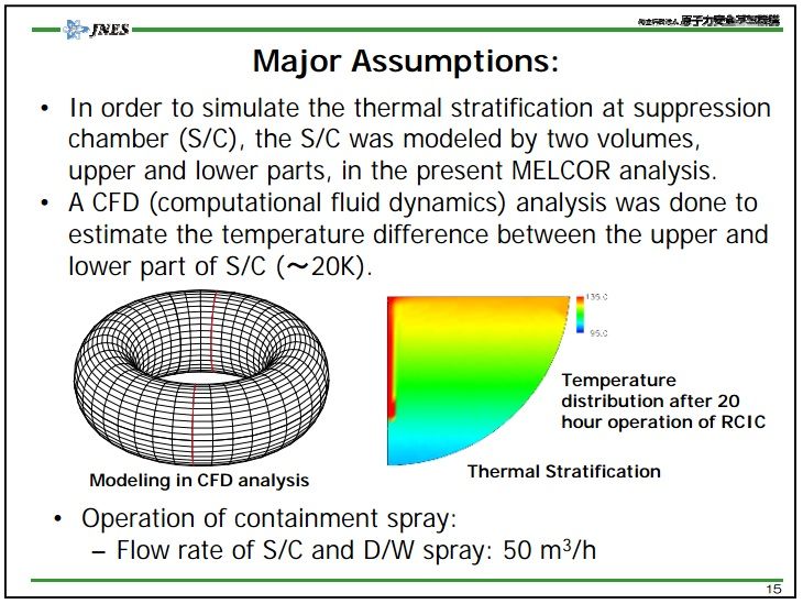
- According to Cook and others (1981), the steam-driven pumps of the RCIC and the HPCI system are set to trip when the temperature near the equipment reaches 93.3 °C. Both pumps suck coolant for the core from the condensate storage tank. Once the tank is exhausted, suction is aligned with the suppression chamber pool. TEPCO operators repeatedly opened the safety relief valves of Units 2 and 3 to release high temperature steam from the reactor pressure vessel into the suppression chamber pool, progressively elevating the water temperature.
In simulations by Hoshi and Hirano (2012), the water exceeded 95 °C at the bottom of Unit 3's suppression pool where the suction head for the RCIC and HPCI systems are located, surpassing the trip points of the RCIC and HPCI pumps. Excess temperature in the suppression pools therefore is a probable cause for these systems at Units 2 and 3 to fail on the third day of the accident (09/03/2013).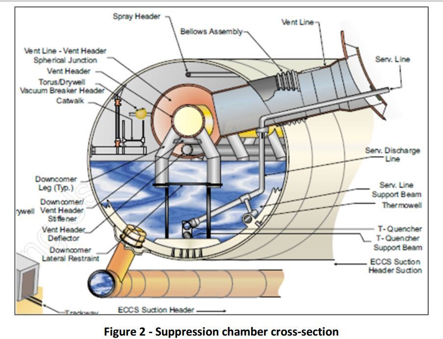
RCIC and HPCI are components of the emergency core cooling system (ECCS). The suction header for the cooling water both systems pump into the reactor pressure vessel is at the bottom of suppression chamber (courtesy: simplyinfo.org).
Simulated suppression pool temperature at Unit 3 (Hoshi H, Hirano M, 2012).


No comments:
Post a Comment